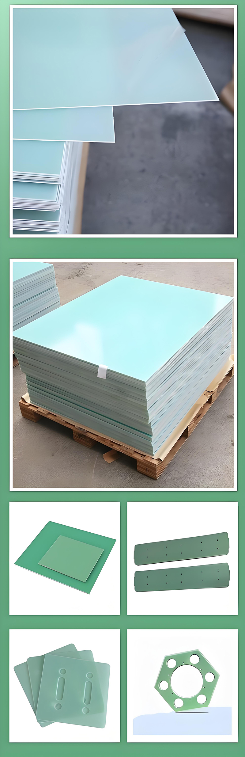
FR4 is one of the most widely used glass fiber reinforced epoxy resin laminate materials in electronics manufacturing, power equipment, and industrial insulation applications. It offers excellent mechanical strength, heat resistance, and electrical insulation performance, while its thickness range is extremely broad—from ultra-thin 0.5mm sheets to heavy-duty 50mm structural boards—covering nearly all applications from precision PCBs to high-voltage insulation support components.
However, in actual procurement and engineering design, many projects still rely mainly on experience when selecting thickness, often overlooking critical factors such as mechanical load, voltage withstand requirements, temperature rise, and machining methods. This can lead either to insufficient structural strength or unnecessary material waste and higher costs. In essence, FR4 thickness selection is a balance between performance, cost, and operational safety.
This article systematically explains the performance characteristics and typical applications of each FR4 thickness range, helping engineers make more reliable and cost-effective decisions under different operating conditions.
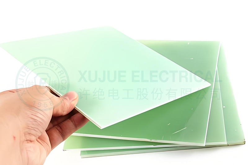
FR4 stands for Flame Retardant Grade 4, a glass cloth reinforced epoxy resin laminate with flame-retardant properties. It is manufactured by impregnating multiple layers of fiberglass cloth with epoxy resin and then compressing them under high temperature and high pressure.
As the number of fiberglass layers increases, the board becomes thicker, and its mechanical strength, bending resistance, insulation withstand capability, and dimensional stability improve accordingly. Because of this highly flexible laminated structure, FR4 can serve both as an ultra-thin precision electronic substrate and as a large insulation structural component in high-voltage electrical equipment.
Understanding the relationship between FR4 thickness and performance is the first step toward accurate material selection.
0.5mm is one of the thinnest commonly mass-produced FR4 thicknesses, mainly used in smart wearable devices, Bluetooth earphones, ultra-thin tablets, and compact sensor modules where lightweight and miniaturization are critical.
This thickness provides some flexibility but relatively low rigidity, making it more prone to warping. Production requires strict SMT precision control and careful reflow soldering temperature management.
0.8mm is widely used in smartphone sub-boards, camera module connection boards, and portable device control boards. Compared with 0.5mm, it offers better rigidity, supports higher-density SMT components, and provides more stable signal integrity.
1.0mm is commonly used for IoT modules, compact controllers, and automotive auxiliary circuit boards. It is particularly suitable for 4-layer to 6-layer PCB designs, providing a good balance between weight control and structural strength.
Industrial sensors and instrumentation control boards often use 1.2mm FR4. This thickness performs better in maintaining drilling precision and significantly improves soldering reliability for fine-pitch package components.
1.6mm is the most common standard FR4 thickness and the default specification for most PCB manufacturers. It is widely used in consumer electronics motherboards, industrial control cards, network communication equipment, and standard control systems.
Because supply is highly mature, processing cost is the lowest, and lead time is shortest, 1.6mm is usually the most economical choice when there are no special project requirements.
2.0mm is commonly used in relay mounting plates, power supply base plates, and medium-sized industrial control backplanes. Its bending rigidity is significantly better than 1.6mm, making it more suitable for mounting heat sinks, connectors, and DIN rail structures.
Variable frequency drive boards, UPS insulation barriers, and phase isolation boards in medium-voltage equipment widely use this thickness range. In many cases, 3.0mm can meet the basic insulation requirements for industrial equipment below AC 600V.
At this thickness level, FR4 is no longer used mainly as a circuit carrier, but more often as busbar support components in high-voltage switchgear, electrical mounting panels, insulation fixtures, and mechanically processed structural parts.
At this stage, high-Tg FR4 is strongly recommended to prevent deformation, delamination, or long-term aging under elevated operating temperatures.
This thickness range is widely used in insulation bases for railway traction systems, guide components for high-frequency welding machines, and insulation positioning blocks inside semiconductor vacuum chambers.
Its main advantages are high dimensional stability and excellent chemical resistance, allowing long-term stable performance even in acid and alkaline cleaning environments.
Transformer insulation spacers, high-voltage test platform insulation panels, and cushioning pads for lamination equipment often use this thickness specification.
Because machining difficulty increases significantly for thick boards, professional CNC milling is usually required, and feed speed must be carefully controlled to prevent delamination and edge chipping.
25mm is commonly used for the main structures of high-voltage isolation devices, electrolytic tank partitions, and large insulation tooling fixtures, especially in applications requiring high dielectric strength.
FR4 thicker than 30mm is usually custom-manufactured, with limited standard stock availability, mainly serving high-end equipment and special operating environments.
For example, precision insulation support structures in large particle accelerators and MRI equipment require extremely high dimensional stability and zero magnetic permeability. Insulation operating rods and mechanical interlock parts in HVDC converter stations must meet both UL94 V-0 flame-retardant rating and IEC 60243 breakdown voltage standards.
Composite insulation support boards used in aerospace ground testing equipment also frequently use this thickness range.
50mm is already close to the practical limit of traditional FR4 lamination technology and often requires multiple pressing cycles. During procurement, it is essential to request internal uniformity inspection reports and Z-axis coefficient of thermal expansion (CTE) data from suppliers to avoid long-term operational risks.
If the board must withstand bolt tightening force, equipment weight, vibration shock, or long-term cantilever loading, bending strength calculations should be the starting point rather than relying on previous experience.
In high-voltage applications, increasing thickness does improve insulation strength, but it cannot fully replace proper creepage distance design. Slotting, insulation paths, and edge treatment are equally important.
Standard FR4 typically has a Tg of around 130°C and is suitable for general industrial environments. For long-term high-temperature applications, high-Tg FR4 (Tg ≥ 170°C) is recommended. If continuous operating temperature exceeds 180°C, PI substrates or ceramic materials are usually more appropriate.
Ultra-thin boards require dedicated fixtures for drilling and slotting, while ultra-thick boards require higher-grade CNC equipment and special dust-control processing measures. In many cases, machining cost differences between thicknesses can be far greater than the raw material cost itself, and must be included in total project cost evaluation.
| Thickness Range | Typical Applications | Performance Focus | Selection Notes |
|---|---|---|---|
| 0.5mm–1.0mm | Consumer electronics, wearable devices | Lightweight, flexibility | Warp prevention, soldering temperature control |
| 1.2mm–1.6mm | General PCB motherboards | Overall balance | Industry standard, preferred choice |
| 2.0mm–3.0mm | Power modules, industrial backplanes | Rigidity, insulation | Match with high-Tg grade requirements |
| 4.0mm–6.0mm | Switchgear barriers, mounting panels | Structural insulation | Calculate creepage distance carefully |
| 8mm–25mm | High-voltage equipment insulation parts | Dielectric strength, stability | Professional CNC machining required |
| 30mm–50mm | Special engineering customization | Extreme comprehensive performance | Confirm internal uniformity reports |
FR4 thickness selection is never a simple single-parameter decision. It is a comprehensive balance involving electrical safety, structural reliability, manufacturing process, and overall project cost.
From ultra-thin 0.5mm boards for consumer electronics to 50mm heavy-duty boards for high-voltage engineering structures, every thickness range has its own clear application logic. The best choice is not always the thickest or the safest, but the one that best matches the actual working conditions.
At the early stage of every new project, engineers are advised to evaluate mechanical load, insulation requirements, operating temperature, and machining method as standard checkpoints. Only through systematic selection can true improvements in reliability, cost control, and delivery efficiency be achieved.
If you need our products please write down any questions, we will reply as soon as possible.
There are three ISO certificates for quality certification. The certificates will be shown later. ISO
After receiving the advance payment, the production cycle is 15-25 days. And the transportation cycle should be calcul……
We supply with installation guide and user manual for each transformer. If you do not understand them. We will offer v……