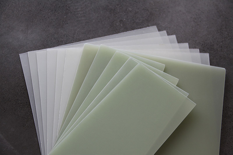
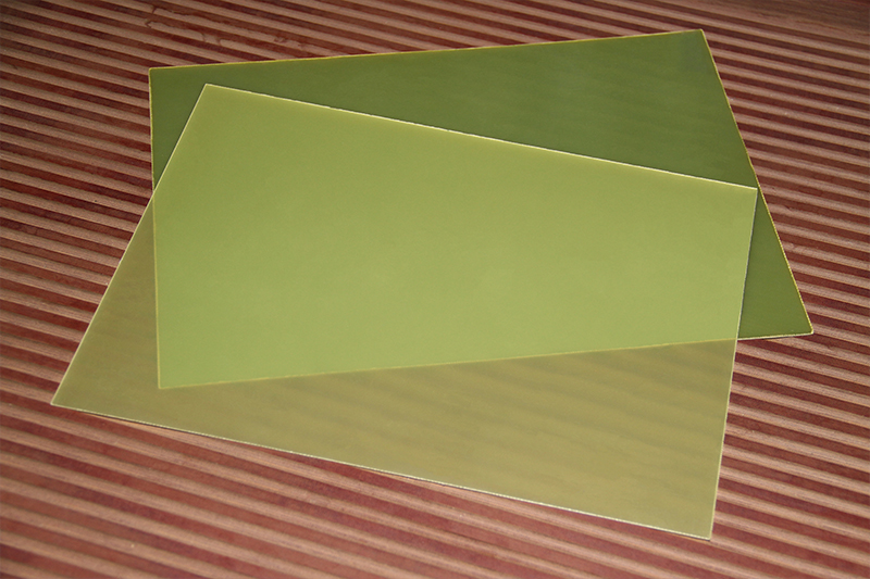
FR4 epoxy fiberglass laminate is one of the most widely used insulation materials in the electronics and electrical industries. With excellent mechanical strength, heat resistance, moisture resistance, and electrical properties, it is applied in countless devices and systems. In practical procurement and engineering design, 1.0mm and 2.0mm FR4 boards are two of the most commonly selected thicknesses. So, how do these two thicknesses differ in terms of strength, electrical performance, and typical applications? This article provides a detailed comparison to help engineers and buyers make more accurate selections.
Rigidity:
The 1.0mm FR4 board offers moderate rigidity and is suitable for most standard electronic devices. Compared with the 2.0mm version, it is more flexible, making it ideal for applications that require slight bending or have limited internal space.
Flexural Strength:
Due to its thinner structure, this board is more prone to bending under external force. However, with proper support in the design, it can still deliver sufficient stability for many applications.
Vibration Resistance:
In high-frequency vibration environments, the reduced thickness of the 1.0mm board may lead to micro-cracks. In such cases, additional structural reinforcement is recommended to compensate for this limitation.
Rigidity:
The 2.0mm FR4 board provides higher rigidity and is suitable for applications that require strong structural support, such as industrial equipment and automotive electronics.
Impact Resistance:
When exposed to mechanical stress or impact, the 2.0mm board can better maintain its structural integrity and significantly reduce the risk of cracking.
Stability:
The thicker board is less prone to deformation in high-temperature or high-humidity environments, making it suitable for harsh operating conditions.
The insulation strength of FR4 is determined by the material itself, but differences in thickness directly affect its withstand voltage (dielectric breakdown voltage). The typical comparison is shown in the table below:
| Thickness | Typical Withstand Voltage Level | Application Recommendation |
| 1.0mm | Relatively lower (but sufficient for most low-voltage circuits) | Suitable for signal boards and high-density wiring boards |
| 2.0mm | Higher | Suitable for high-voltage circuits, power modules, and isolation barriers |
From this comparison, it is clear that when an application requires higher dielectric strength or larger safety clearance, the 2.0mm FR4 board is the more appropriate choice.
Inner layers of multilayer PCBs, suitable for high-density routing
Thin, lightweight insulation barriers in electronic devices
Insulating components inside small electronic equipment
Light-duty structural parts, such as small-power power-supply brackets
Internal components of compact terminal devices
Parts that require higher flexibility, or insulating pieces that need bending or thermoforming during processing
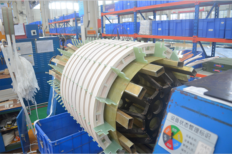
Structural components in power equipment, such as supports in transformers and switchgear
Insulating parts that need to withstand mechanical pressure
High-voltage insulation applications, including high-voltage isolation plates and carrier boards for power control modules
Heat-sink mounting bases or carrier plates (the 2.0mm board is more stable and less prone to deformation)
Heavy-load mechanical components, such as motor slot wedges
Structural support parts used in industrial machinery
A 1.0mm FR4 board is more suitable for lightweight applications such as electronic circuits, small devices, and low-load insulation barriers.
In contrast, a 2.0mm FR4 board is better suited for heavy-duty applications that require higher mechanical strength, greater dielectric withstand capability, or robust insulation structures in power equipment.
During engineering selection, factors such as mechanical strength, electrical safety, device size, and heat dissipation conditions must all be considered. Choosing the appropriate FR4 thickness not only enhances equipment safety but also helps optimize costs and extend the service life of the device.
If you need our products please write down any questions, we will reply as soon as possible.
There are three ISO certificates for quality certification. The certificates will be shown later. ISO
After receiving the advance payment, the production cycle is 15-25 days. And the transportation cycle should be calcul……
We supply with installation guide and user manual for each transformer. If you do not understand them. We will offer v……